Join us in wishing Simon all the best with his retirement and read his words of advice.
Transducer News & Views | The Applied Measurements Blog
Come and Chat with Our Friendly Team at Silverstone Race Circuit

Join us for a FREE day out at EIS Instrumentation, Analysis and Testing Exhibition May 16, 2023, Silverstone Race Circuit.
Bob Davies is Celebrating His Retirement

Exclusive interview with our Production Director of 23 years. Join Bob as he talks about his earliest memories and achievements at Applied Measurements.
NEW Portable Strain Gauge Display – In Stock & Available Now
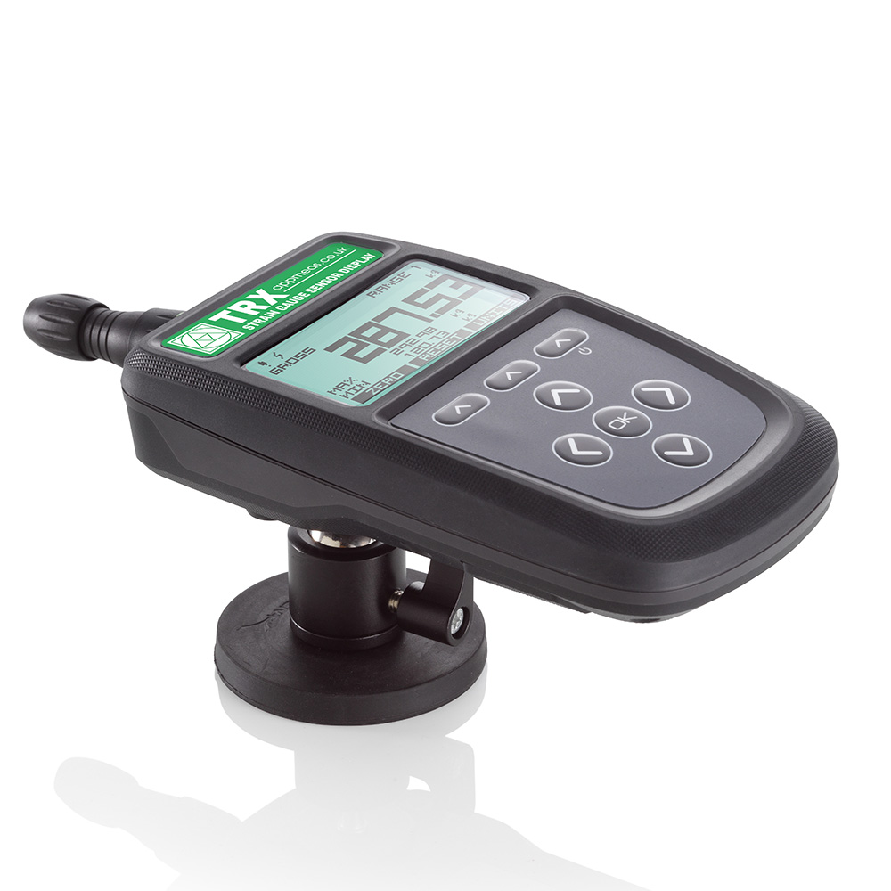
The new TRX strain gauge display with integrated TEDS functionality is available to order online, UK stock, next day delivery.
We are Cyber Essentials Certified

Applied Measurements are proud to be awarded the Cyber Essentials Certification which demonstrates our commitment to your cyber security.
FREE Techfolio for Your Stories
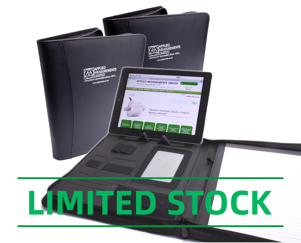
We would love to give you the opportunity to showcase your application stories on our website.
Tell us where and how you use our products.
Get 10% Off Our Online Shop at Silverstone Race Circuit
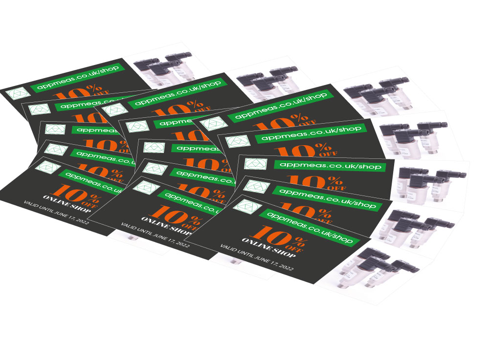
Visit Applied Measurements at EIS exhibition May 17, 2022 to receive a 10% voucher for our online shop.
OEM Pressure Sensors UK-Made and High Volume
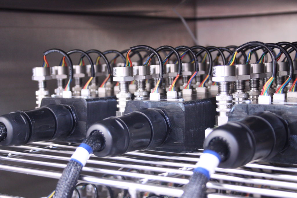
Applied Measurements OEM pressure sensors are made in the UK so we can guarantee precise and high-quality sensor manufacture. Fast scheduled deliveries available.