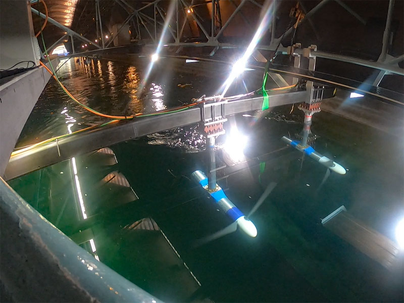
Read how our dual axis force and torque sensors was used in tidal testing by the University of Oxford. They aimed to understand how the spacing between tidal turbines and different control strategies affects the performance of tidal turbines.
Category: Case Studies
Here is a selection of incredible case studies and application stories of our products being used in our customer’s diverse applications, from aerospace, food & pharmaceutical, geotechnical, subsea to R&D.
Plus, read our published sensor application papers and journals which show detailed specific applications using our products.
If you and your company are happy with our services and products please share your Applied Measurement success story with us.
Applied Measurements Load Cells in World’s First Regenerative Fatigue Test Facility
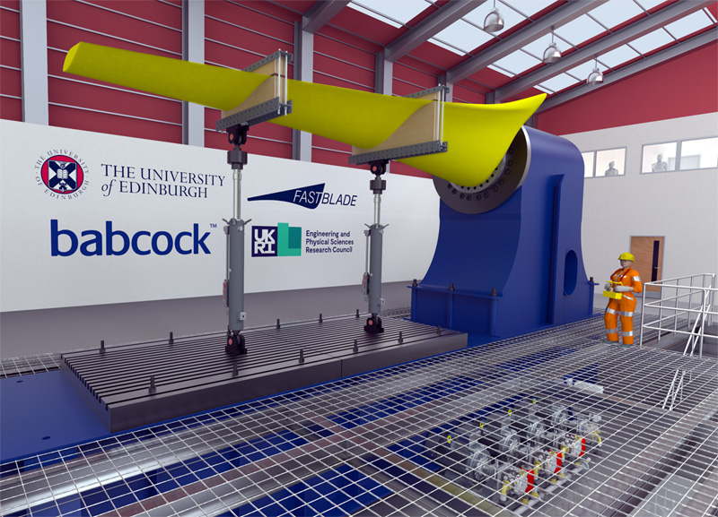
Developed by the University of Edinburgh, FASTBLADE is designed for high-quality, low-cost fatigue testing of tidal turbine blades, composite bridge sections and carbon fibre aircraft wing boxes and is the world’s first test facility that uses regenerative hydraulic technology.
Thanks to its cost-effective and accelerated testing, FASTBLADE reduces design risks, delivers rapid evaluation and enables faster certification and deployment of new products to the global market.
Applied Measurements DSCC precision pancake load cells are an integral part of FASTBLADE’s design. They are low profile, high accuracy and have a high-frequency response.
Find out more…
5 Reasons This May Be the Best Load Cell for Plate Bearing Tests
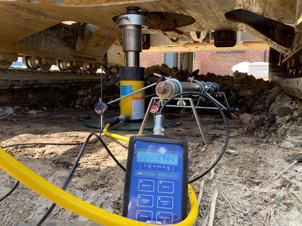
Micro Geotechnical, an in-situ testing company, needed to accurately monitor the bearing capacity of the ground under a given load, to determine the safe bearing capacity of the soil.
The measuring instruments would need to be accurate and precise, with the ability to withstand the harsh outdoor environments of their in-situ plate bearing tests.
So, we offered them Applied Measurements button load cell CBES and our handheld indicator and here’s why…
How to measure grip strength of an eagle for BBC Natural World
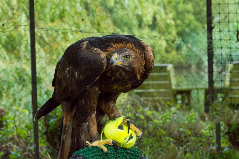
Last year, we were asked to design a sensor to measure the grip strength of a golden eagle named Tilly, for the award-winning BBC documentary series, Natural World.
Challenge – to find a load cell that could withstand the estimated grip strength of an eagle.
As Tilly had been trained to catch and grip a tennis ball, the load cell needed to be small enough to fit inside a similar-sized measuring device yet withstand Tilly’s tremendous grip strength.
Thanks to their unique design, our DBBSMM miniature s-beam load cells were ideal for the job. Not only are they very compact but their s-shaped design offers superior side-load rejection and high accuracy.
State-of-the-Art Sensors for Oldest Working Beam Engine in the World
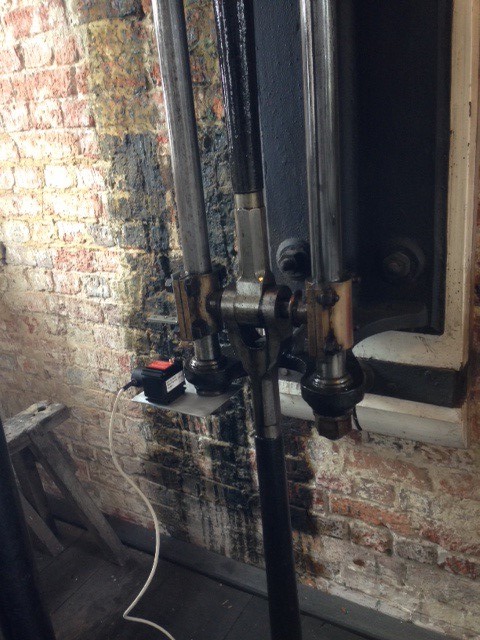
The Boulton and Watt steam engine, originally installed in 1812, is the oldest working beam engine in the world.
It is on this 200-year-old steam engine that engineers want to install the latest state-of-the-art sensors and instrumentation to monitor position, speed and acceleration of the piston.
This Mechatronics Project – ‘marrying 200 years of technology’ – has 5 main aims.
- To understand the impact on the engine when running at full load.
- To explore engine efficiency.
- To illustrate to visitors the internal workings of the engine in real-time.
- To display information to less-able visitors unable to climb the stairs.
- To provide data for educational and research projects at all levels.
Read how they monitored the position of the piston.
5 Reasons to Use Our Pressure Sensors in Your Diesel Injector Tester
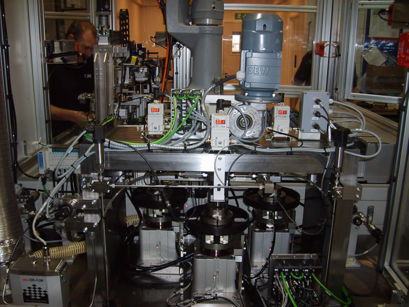
Curtis Assemble & Test Ltd, a designer and manufacturer of high-performance automotive test machines, use our pi600 industrial pressure sensors in their diesel injector valve pressure tester.
“We choose to use Applied Measurements pressure transducers on our machines due to the reliability and competitive pricing. For us they are a fit and forget part,” explains Mark Hobday, Technical Development Engineer, Curtis Assemble & Test Ltd.
Load cells deliver high accuracy in Gemini Telescopes even after 20 years!

20 years ago, we were approached by The Royal Greenwich Observatory in Cambridge to design and build nearly 700 bespoke load cells for two 8.1m diameter telescopes known as The Gemini Project.
Now 20 years on, these custom-made load cells are still consistently and accurately performing an integral part of the telescope’s control system.
To continue to deliver accurate and detailed astronomical images, we have been asked to re-design and manufacture custom load cells to the same specifications incorporating up-to-date electronics with the latest state-of-the-art amplifiers.
See how we did it.
Why United Utilities Chose Us To Keep The Water Flowing
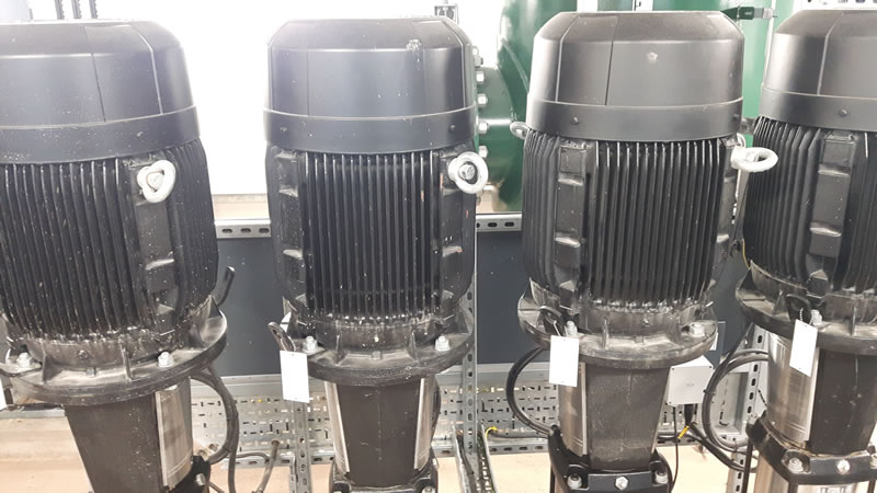
United Utilities needed a way to monitor the constantly changing water level in their water treatment plant to guarantee a steady flow of water into the reservoir.
Learn how they did it using our level transmitters.