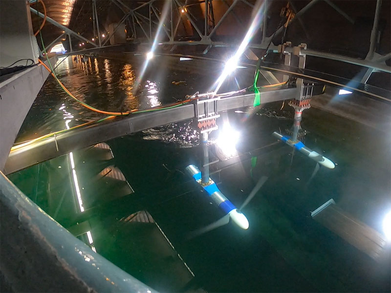
Read how our dual axis force and torque sensors was used in tidal testing by the University of Oxford. They aimed to understand how the spacing between tidal turbines and different control strategies affects the performance of tidal turbines.
Category: Torque
Real Life: Power Take-Off Torque Monitoring – Accurate, Fast and Simple!
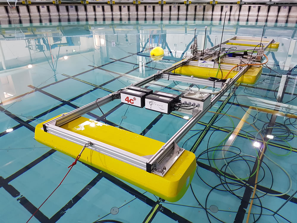
Read the real life case study of power take-off torque monitoring on the Wave Energy Converter The SeaPower Platform. See how our complete torque measuring system enabled engineers to accurately monitor the torque applied by the Wave Energy Converter as it responded to waves in the test tank with accurate, fast and reliable results.
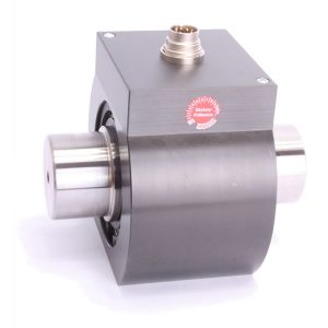
NEW DRVL Rotary Torque Transducer Promises Enhanced Compatibility
 The new DRVL rotary torque transducer features:
- Greater Compatibility with a Range of Evaluation Devices
- Offers 2 Output Standard Signals (10V and 10kHz ± 5kHz)
- Has an Increased Speed Range
- High Accuracy to 0.1% (0.05% Optional)
- Is Cheaper to Buy
Read this article to find out more.
Get Instant Rotary Torque Measurements Without Additional Indicator
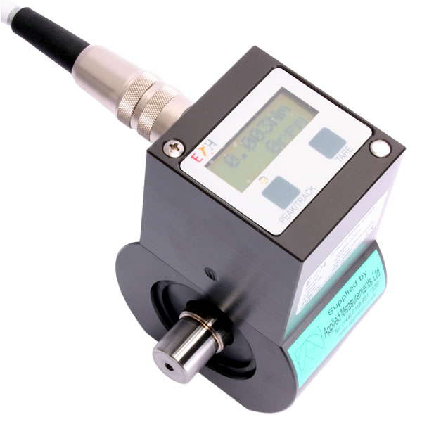
 The DRBK-A rotary torque transducer with display is ideal to use if you want a simple to read real-time speed/torque display without any extra analysis.
- Instant Speed/Torque Display
- Low Cost as No Additional Instrumentation Needed
- Compact with its Built-In Display
- Real-Time Speed Updates of 1 x Sample/Second
Incredible Miniature Reaction Torque Sensor Helps Create Ocean Energy
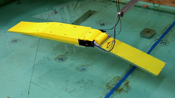
The YDNS miniature reaction torque sensor’s compact size and in-line direct drive measurement capability meant it could easily be housed within the waterproof enclosure of the 1/50th scale wave energy converter.
Low Cost Rotary Torque Transducers Now Available with Lower Capacities
 We can now offer you lower capacity versions 0.5Nm, 1Nm and 2Nm giving you improved measurement accuracy in lower-torque applications such as small gearbox and low-power motor testing.
New Range of Rotary Torque Transducers
Applied Measurements are pleased to announce exclusive UK distribution of a new range of brushless rotary torque transducers from German manufacturer ETH Messtechnik. ETH were chosen for the very high performance capabilities and exemplary quality of their torque sensors which will compliment our own existing range of rotary and static types. Initially we have introduced five torque sensors to our range, here is a brief summary of each model: DRBK – A compact and low cost shaft type torque sensor available with capacities from 0-5Nm up to 0-1000Nm, maximum speeds up to 22,000rpm and a ±5Vdc conditioned output signal. A pulsed speed/RPM output is optional. DRFL – A compact, high performance shaft type torque sensor with an accuracy class of […]
Rotary Wireless Torque Transducers Use Battery-Powered 2.4GHz Telemetry
Applied Measurements are proud to introduce the DTDR-F rotary wireless torque transducer, a novel design that expunges stator coils and inductive transmission systems from the design brief in favour of a cutting edge, battery-powered 2.4GHz wireless telemetry data acquisition and transmission system. The DTDR-F design is based on the DTD-F torque transducer, a flanged device designed for use in static and quasi-static torque measurement applications, with modifications to allow the incorporation of a pair of balanced Delrin housings, one containing the telemetry acquisition and transmission module and the other containing a 3.6V high capacity lithium-ion (Li-Ion) battery that is recharged in-situ. The DTDR-F is intended primarily for use in rotating applications at speeds of up 6500rpm where a direct, in-line […]