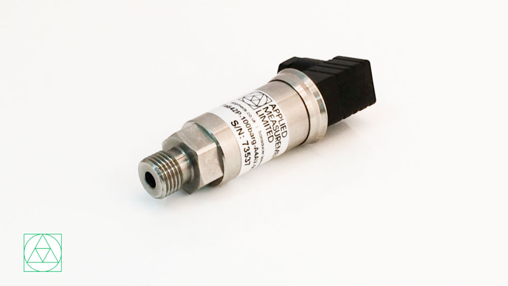
The new Pa600-LR low pressure sensors can accurately measure from as little as 0-50mbar in pressure. Order yours today.
Transducer News & Views | The Applied Measurements Blog
Digital Pressure Measuring in 3 Easy Steps
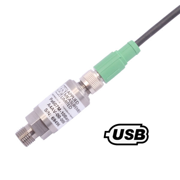
Our state-of-the-art digital pressure sensors are high accuracy AND come with a high resolution, high-speed USB interface. This means you can quickly and easily view the pressure results on your PC or laptop in real-time.
What’s more, all this digital pressure measuring can be done in 3 easy steps.
Visit Us at Silverstone Race Circuit 14th September 2021

Come and chat to us at stand 37, 14th September 2021, Silverstone Race Circuit. See live demonstrations and view our latest product range.
Buy Online! More Sensors Added to Webshop
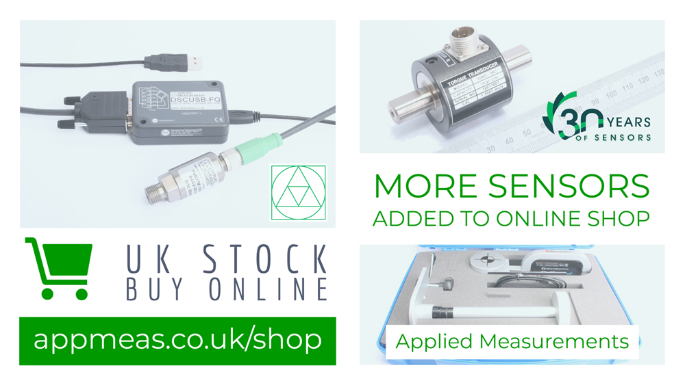
You can easily order not just one sensor but multiple sensors. Plus, you can add on accessories, instrumentation and various calibration options. Our drop-down menus make it easy for you to see the ranges, cable lengths and special options available for that sensor and their pricing.
How to Quadruple Your Digital Pressure Speed Without Lowering Its Quality
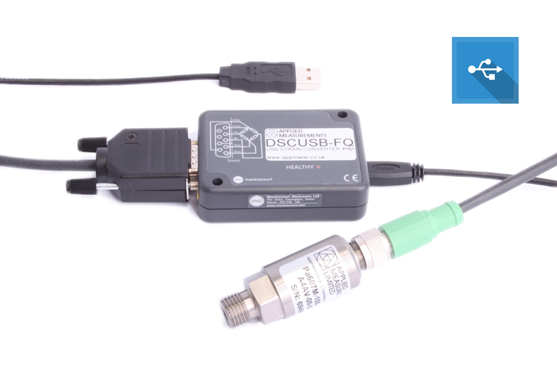
Do you want faster digital pressure measurements? Look no further than Applied Measurements new dynamic digital pressure sensor. The Pa600-USB-FQ has a naturally high-frequency response, boasting a fast sampling rate of 4.8kHz along with a resolution of up to 1 part in 8,000, thanks to its 24-bit ADC circuit sampling. This means you can have super-fast pressure measurement results on your PC or laptop.
Applied Measurements Promise Precise Thrust & Torque Results in Tidal Turbine Testing
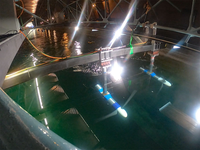
Read how our dual axis force and torque sensors was used in tidal testing by the University of Oxford. They aimed to understand how the spacing between tidal turbines and different control strategies affects the performance of tidal turbines.
UK-Made OEM Pressure Sensors – Small, Medium and High Volume
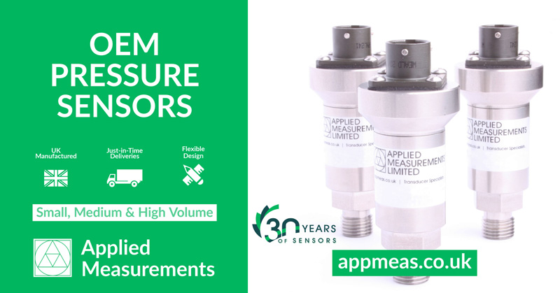
We have expanded our UK pressure manufacturing and can give you low cost, small, medium and high volume OEM pressure sensors.
We have UK stock holding of component parts so we can offer you just-in-time and fast scheduled deliveries.
Our 5 Steps That Keep Load Cell Design Easy
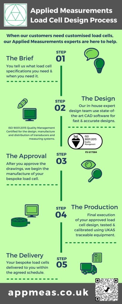
Do you need a unique load cell design for your application? How about an exact replacement for your existing one? See our 5 steps of our easy load cell design process.