


Other ranges: 12 weeks
At a Glance
- Capacities: 0-1kg up to 0-30,000kg
- Output: 2mV/V to 2.7mV/V
- Environmental Protection: IP51
- High Accuracy: <±0.03%/RC
- Custom Versions Available
- Dual Bending Beam and Shear Web Designs
- High Performance
- Optional IP67 Sealing for Harsh Environments
- Fully Submersible Marine & Offshore Versions
- Standard or Customised Mounting Bases and Design Fixtures
- Rod Ends and Load Buttons Available
Description
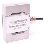
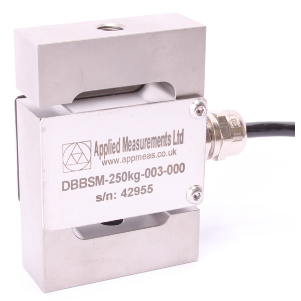
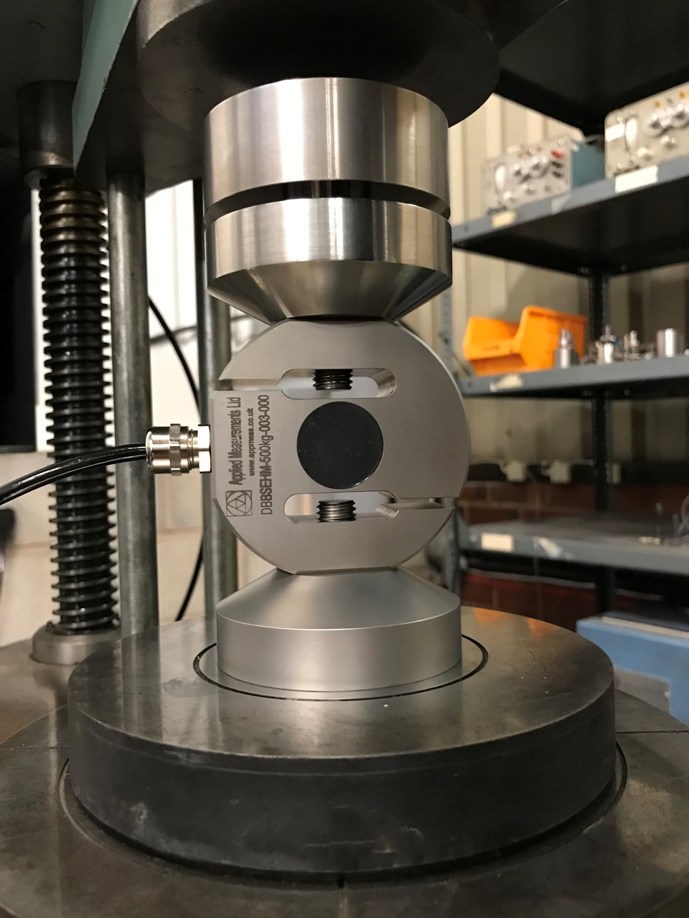
Applied Measurements DBBSM universal load cell is suitable for tension or compression. It lends itself to a wide force and load measurement applications such as those found on tensile testing machines, suspended hoppers and geotechnical test equipment, as well as a wide range of other general purpose applications.
Our s-beam load cells are available to buy online from our webshop, with the 0-5000kg ranges in stock.
Our universal load cell features a dual bending beam sensing design on all capacities up to 1000kg, while a shear web sensing design is used from 2500kg upwards. Both designs offer excellent accuracy and are guaranteed to meet a specification of ±0.03% of the rated capacity of better.
Applied Measurements rod-end bearings and load buttons are available (see gallery images) to suit all universal load cell capacities and provide optimal loading conditions to ensure that you get the best possible performance from your measuring system. Plus, our expert knowledgeable team can customise the DBBSM s-beam load cell to suit your specific application.
If you need to fit into a restricted space, our DBBSMM range of miniature S-Beam load cells will fit the bill.
We chose Applied Measurements’ DBBSM s-beam load cells as the pigment is £1000 per tonne so has to be extremely accurate.
Paul Akers, Works Manager, PD Edenhall Ltd
Technical Specifications
| Rated Capacity (RC) | kgf | 0-1, 0-2, 0-5, 0-10, 0-25, 0-50, 0-100, 0-250, 0-500, 0-1000, 0-2500, 0-5000, 0-10,000, 0-20,000, 0-30,000 |
|---|---|---|
| Operating Modes | Tension / Compression / Tension & Compression | |
| Sensitivity (RO) | mV/V | 2.7 nominal (2.0 nominal on 10,000kgf and above) |
| Zero Balance/Offset | ±%/Rated Output | <1.0 |
| Zero Return after 30 mins | ±%/Applied Load | <0.03 |
| Output Symmetry (tension vs. compression) | ±%/Rated Output | 0.1 to 0.25 typical |
| Non-Linearity | ±%/Rated Output (BFSL) | <0.03 |
| Hysteresis | % / Rated Output | <0.03 |
| Repeatability | ±%/Rated Output | <0.02 |
| Temperature Effect on Zero | ±%/Rated Output/˚C | <0.005 |
| Temperature Effect on Sensitivity | ±%/Applied Load/˚C | <0.005 |
| Input Resistance | Ohms | 375-420 nominal |
| Output Resistance | Ohms | 340-360 nominal |
| Insulation Resistance | Megohms | >5000 @ 50Vdc |
| Excitation Voltage | Volts AC or DC | 10 recommended (2-15 acceptable) |
| Operating Temperature Range | ˚C | -20 to +80 |
| Compensated Temperature Range | ˚C | 0 to +70 |
| Storage Temperature Range | ˚C | -20 to +80 |
| Safe Overload | % of Rated Capacity | 150 |
| Ultimate Overload | % of Rated Capacity | 200 |
| Maximum Safe Side Load | % of Rated Capacity | 30 |
| Deflection @ Rated Capacity | mm | see dimensional table |
| Fundamental Resonant Frequency* | Hz | see dimensional table |
| IP Rating (Environmental Protection) | IP51 (IP67 optional 50kg capacity and higher only) | |
| Weight (excluding cable) | kg | see dimensional table |
| Fatigue Life | Consult Sales | |
| Cable Length (as standard) | metres | 3 |
| Cable Type | 4-core screened, PUR sheath, Ø5 | |
| Construction Material | 1kg-100kg: Aluminium Alloy / 250kg-30,000kg: Stainless Steel | |
| Resolution | 1 part in 250,000 (with appropriate instrumentation) | |
| *The resonant frequency is calculated with the body of the load cell attached to a large plate, ensuring that only the sensing element oscillates: This is vital to achieve the highest natural frequency and subsequent frequency response. | ||
Product Dimensions
Rated Capacity (kgf) | H | L | W | W1 | G | G1 | Threads T | Deflection mm | Weight kg | Resonant Frequency Hz |
|---|---|---|---|---|---|---|---|---|---|---|
1, 2, 5, 10, 25 | 60 | 48 | 12.7 | 20 | 30 | 6.35 | M8 x 1.25 | 0.55; 0.58; 0.51; 0.41; 0.36 | 0.085 | 94; 130; 212; 326; 536 |
50, 100, 250 | 70 | 48 | 18 | 25 | 35 | 9 | M8 x 1.25 | 0.41 | 0.14; 0.14; 0.33 | 530; 740; 715 |
500, 1000 | 75 | 48 | 30 | 37 | 37.5 | 15 | M12 x 1.75 | 0.41; 0.56 | 0.56; 0.58 | 760; 900 |
2500, 5000 | 90 | 63 | 38 | 38 | 45 | 8 | M16 x 2.0 | 0.33; 0.43 | 1.33; 1.35 | 1200; 1700 |
10,000 | 145 | 138 | 55 | N/A | 72.5 | 27.5 | M30 x 2.0 | 0.16 | 7.2 | 1600 |
20,000, 30,000 | 190 | 183 | 70 | N/A | 95 | 35 | M45 x 3.0 | 0.16; 0.16 | 16;16 | 1100; 1400 |
| Note: Capacities of 10,000kg and up have rounded shoulders |
All dimensions are in mm
Wiring Details
| Wire | Designation |
|---|---|
| Red | +ve excitation |
| Blue | -ve excitation |
| Green | +ve signal (tension) |
| Yellow | -ve signal |
| Screen | To ground - not connected to load cell body |
Ordering Codes & Options
| Core Product | Capacity (inc Engineering Units) | Cable Length (m) | Specials Code | Example Result |
|---|---|---|---|---|
| DBBSM | 1kg | 003 | 000 | DBBSM-1kg-003-000 |
| DBBSM | 2kg | 003 | 000 | DBBSM-2kg-003-000 |
| DBBSM | 5kg | 003 | 000 | DBBSM-5kg-003-000 |
| DBBSM | 10kg | 003 | 000 | DBBSM-10kg-003-000 |
| DBBSM | 25kg | 003 | 000 | DBBSM-25kg-003-000 |
| DBBSM | 50kg | 003 | 000 | DBBSM-50kg-003-000 |
| DBBSM | 100kg | 003 | 000 | DBBSM-100kg-003-000 |
| DBBSM | 250kg | 003 | 000 | DBBSM-250kg-003-000 |
| DBBSM | 500kg | 003 | 000 | DBBSM-500kg-003-000 |
| DBBSM | 1000kg | 003 | 000 | DBBSM-1000kg-003-000 |
| DBBSM | 2500kg | 003 | 000 | DBBSM-2500kg-003-000 |
| DBBSM | 5000kg | 003 | 000 | DBBSM-5000kg-003-000 |
| DBBSM | 10,000kg | 003 | 000 | DBBSM-10,000kg-003-000 |
| DBBSM | 20,000kg | 003 | 000 | DBBSM-20,000kg-003-000 |
| DBBSM | 30,000kg | 003 | 000 | DBBSM-30,000kg-003-000 |
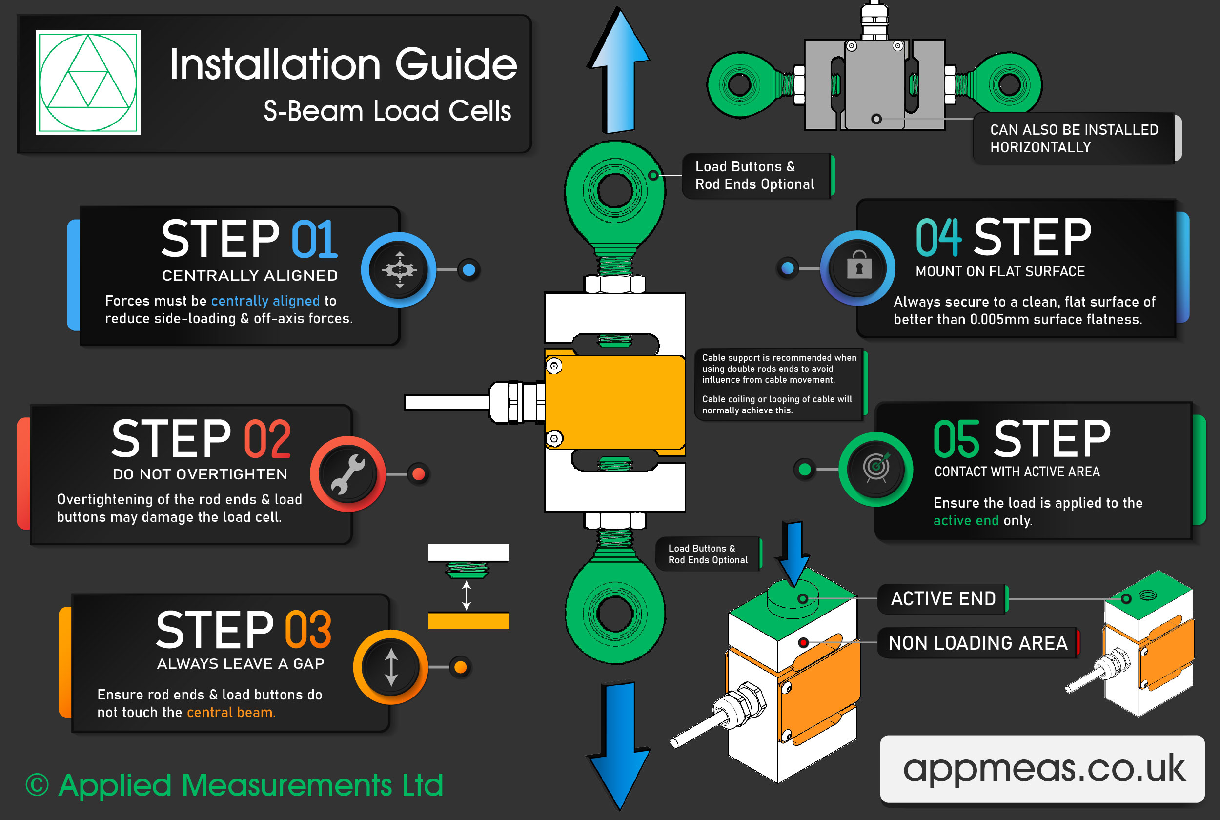
How to Install an S-Beam Load Cell
Our Applied Measurements experts have put together a 5-step guide to demonstrate how to correctly install an S-beam load cell.
Step 1 – Keep the Forces Centrally Aligned
To reduce any off-axis loading, forces must be centrally aligned through the centre of the load cell. We can supply optional load buttons and rod ends which work to reduce any side loading.
Step 2 – Do Not Overtighten the Rod Ends and Load Buttons
When using rod ends and load buttons be sure not to overtighten them when attaching them to the S-beam load cell. As this can cause damage to the load cell.
Step 3 – Always Leave a Gap
Ensure that the rod ends and load buttons do not touch the central beam. If a gap is not maintained, the central beam will not be able to move freely when tension or compressive force is applied.
Step 4 – Mount on a Flat Surface
Always secure the S-beam load cell to a clean, flat surface of better than 0.005mm surface flatness.
Step 5 – Contact with Active Area Only
When installing the S-beam load cell ensure the load is applied to the active end area only.
Mounting and Installation Accessories
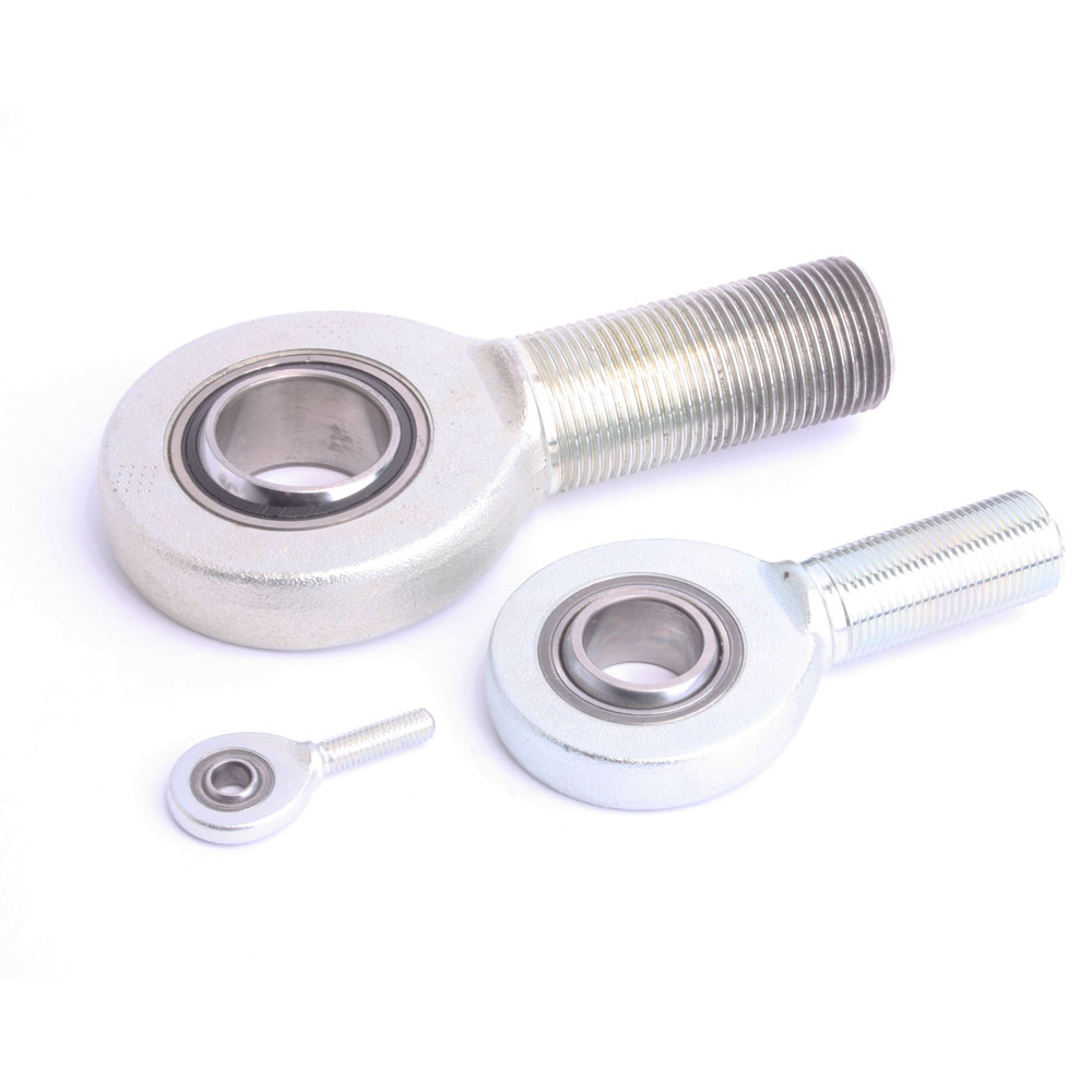
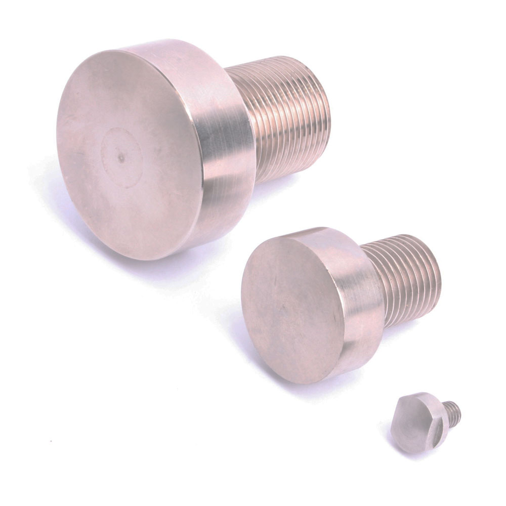
Load Buttons and Rod End Bearings
Designed to align forces through the principle axis of the load cell thus reducing the effects of extraneous forces, hence offering improved performance from the cell.
Load buttons are used where compressive forces are applied.
Rod End Bearings are used where tensile forces are being applied.
Load Buttons for Compression Use
| THREAD T | M8 x 1.25 | M12 x 1.75 | M16 x 2 | M24 x 2 | M30 x 2 | M45 x 3 |
|---|---|---|---|---|---|---|
| D | 15 | 22 | 32 | 26 | 50 | 70 |
| H | 5 | 6 | 10 | 14 | 20 | 40 |
| L | 10 | 12 | 16 | 26 | 40 | 60 |
| R | 150 | 150 | 180 | 200 | 200 | 300 |
Rod End Bearings for Tension Use
- Supports radial loads in a tensile or compressive direction.
- Suitable for unilateral loads – can support alternating loads and alternating loads in combination with bearing GE..UK-2RS.
- Zinc plated for corrosion resistance.
- Are maintenance-free (in bearings with Elgoglide®, lubricant leads to a considerable reduction in bearing life)
- Fitted with radial spherical plain bearings GE..UK or GE..UK-2RS
- Hard chromium/PTFE composite or hard chromium/Elgoglide® sliding contact surfaces.
- Enables compact adjacent construction thanks to its thin walled design of the eye housing.
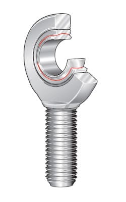
GAR..UK
(right hand thread)
GAR..UK-2RS
(right hand thread)
- To ISO 12 240-4, dimension series E, type M
- Shank with external thread
- Suffix -2RS: lip seals on both sides, for operating temperatures from -30°C to +130°C
- GAR..UK and GAL..UK for shaft diameters from 6mm to 30mm
- GAR..UK-2RS and GAL..UK-2RS for shaft diameters from 35mm to 80mm
Maintenance-free
ISO 12 240-4, dimension series E, type M
Sliding contact surface: hard chromium/PTFE
Series GAR..UK
Sliding material: PTFE composite
GAR..UK-2RS
Sliding material: Elgoglide®
| LOAD CELL | SHAFT DIAMETER | ORDERING CODE | MASS | DIMENSIONS | |||||||
|---|---|---|---|---|---|---|---|---|---|---|---|
| d | WITHOUT SEALS | WITH SEALS | ≈ kg | d | D | B | dK | d1 | d2 | d3 | |
| DBBSM-1kg to 250kg | 8 | GAR 8 UK | - | 0.029 | 8-0.008 | 16 | 8-0.12 | 13 | 10.2 | 24 | M8 |
| DBBSM-500kg to 1000kg | 12 | GAR 12 UK | - | 0.086 | 12 -0.008 | 22 | 10-0.12 | 18 | 14.9 | 34 | M12 |
| DBBSM-2500kg to 5000kg | 17 | GAR 17 UK | - | 0.19 | 17-0.008 | 30 | 14-0.12 | 25 | 20.7 | 46 | M16 |
| DBBSM-10,000kg | 30 | GAR 30 UK | - | 0.89 | 30-0.01 | 47 | 22-0.12 | 40.7 | 34.2 | 73 | M30x2 |
| DBBSM-20,000kg to 30,000kg | 50 | - | GAR 50 UK-2RS | 3.4 | 50-0.012 | 75 | 35-0.12 | 66 | 55.9 | 112 | M45 x 3 |
| TYPE | Degrees | Chamfer Dimension | Basic Load Ratings 1) | Radial Internal Clearance | Shaft Diameter | ||||||
|---|---|---|---|---|---|---|---|---|---|---|---|
| h | C1 | α | l1 | l2 | l7 | r1s min. | dyn. Cr N | stat. C0r N | d | ||
| DBBSM-5kg to 250kg | 42 | 6 | 15 | 22 | 54 | 14 | 0.3 | 5 850 | 12 900 | 0 - 0.032 | 8 |
| DBBSM-500kg to 1000kg | 54 | 8 | 11 | 28 | 71 | 18 | 0.3 | 11 400 | 30 100 | 0 - 0.032 | 12 |
| DBBSM-2500kg to 5000kg | 69 | 11 | 10 | 36 | 92 | 23 | 0.3 | 22 400 | 56 500 | 0 - 0.04 | 17 |
| DBBSM-10,000kg | 110 | 19 | 6 | 65 | 146.5 | 37 | 0.6 | 65 500 | 138 000 | 0 - 0.05 | 30 |
| DBBSM-20,000kg to 30,000kg | 185 | 30 | 6 | 107 | 241 | 60 | 0.6 | 442 000 | 313 000 | 0 - 0.06 | 50 |
| 1) Basic load rating of housing. | |||||||||||
| In rod ends with the sliding material Elgoglide®, the basic load rating C0r of the housing is less than the basic dynamic load rating Cr of the bearing. | |||||||||||
Due to our policy on ongoing development, dimensions and specifications may change without notice.
Downloads
CAD Model Files
Our 3D models are provided in STEP format and can be viewed using FreeCAD. Other formats can be provided on request.
The .zip file below contains a separate model for each product variant.
Instant Price & Part Code Builder
You can now buy this product in our online shop. Alternatively, you can find the ordering code, price* and lead time below.
Product Details
- Price*
- Lead Time
- Part Code
*Please note: The prices shown are valid in the UK only and do not include carriage charges. For overseas pricing please contact a member of our sales team or your local distributor.
Case Studies
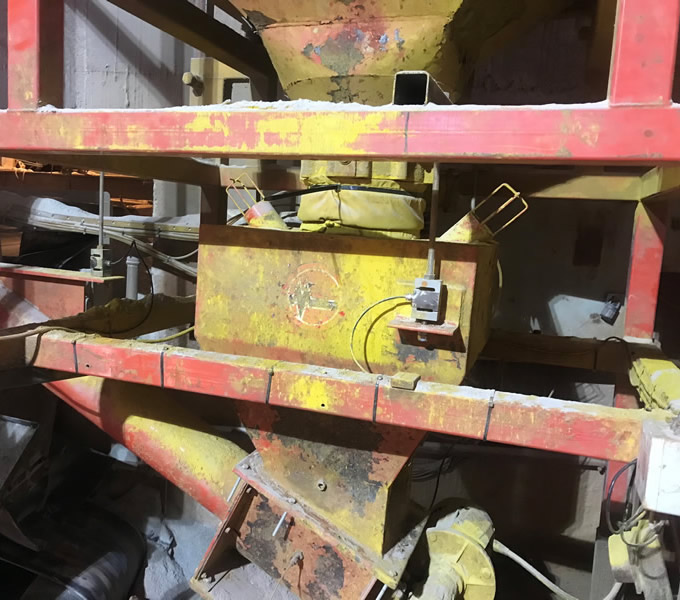
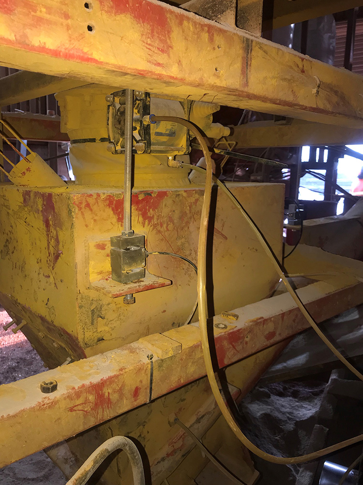
S-Beam Load Cells Promise Accurate Pigment Dispensing
We chose Applied Measurements’ DBBSM s-beam load cells as the pigment is £1000 per tonne so has to be extremely accurate” says Paul Akers, Works Manager at PD Edenhall Ltd. One of the largest independent concrete facing brick manufacturer in the UK, needed a way to accurately monitor the amount of pigment being dispensed into the weigh hopper throughout the manufacture of concrete facing bricks. The pigment amount needs to be precise as inaccurate amounts of pigment can lead to incorrect colour blends leading to a loss in sales and profit. Read how our accurate DBBSM s-beam load cells and intuitive4-L digital indicators were used in this construction industry application.
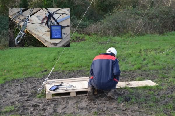
Complete Tensile Monitoring System Delivered in Under 1 Week
With huge capacities of up to 30,000kg and an accuracy of <±0.03% of the rated capacity, the highly accurate DBBSM S-beam load cell really is the knight in stainless steel armour. Not only can it efficiently handle the larger loads in the guys, it can also be supplied in less than 1 week! Its tough construction makes it ideal to use in the harsh outdoor conditions on the guy cables.

Force Measurement Determines The Effect of Girth Tension on Horse Gait
Using electrical systems for the measurement of mechanical forces is by no means limited to machines and laboratory based applications. In her recently completed research thesis ‘Girth Tensions and their Effects on Equine Stride Characteristics’, Sue Wright of Moulton College Northampton used load cells, motion sensors and GPS amongst other technologies to measure and record the tension within the girth strap used to hold the saddle in place.
Why Applied Measurements?
- Suppliers of top quality strain gauge sensors and transducers to every corner of industry - UK and worldwide
- Over 100 years of expert transducer knowledge
- Our high quality products all come with a 3 year warranty
Related Products
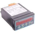
 Load Cell Digital Indicator | High Accuracy | Intuitive4-LHighly configurable, modular constructionFrom £364Buy Online
- Handheld Load Cell Indicator | Digital Display | TR150From £495Buy Online
- T24 Wireless Telemetry
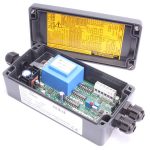
- Load Cell Amplifier | Load Cell Signal Conditioner | SGAInputs from 0.06mV/VFrom £235Buy Online
- USB Load Cell Interface | DSCUSB100 Readings/Second max.From £335Buy Online


Popular Products
- Platform Load Cell | Single Point Load Cell | 0-250g to 0-40kg | OBUG0-250g to 0-40kgFrom £128Buy Online
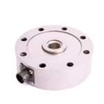
- Pancake Load Cell | Low Profile Force Sensor | DSCC0-5kN up to 0-1000kNFrom £651Buy Online
- Universal Load Cell | Universal S-Beam Force Sensor | DBBSM0-1kg up to 0-30,000kgFrom £269Buy Online
- Handheld Load Cell Indicator | Digital Display | TR150From £495Buy Online
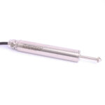
- Strain Gauge Displacement Sensor | Linear Position Sensor | AML/SGD0-5mm to 0-100mmFrom £429Buy Online