It can be very difficult to choose the right output from a sensor as there are many different options, and it is important to understand how they work in order to get a good working system.
One of the amplified sensors commonly used is the two-wire 4-20mA current loop or 10-50mA system. This is easy electrical wiring, with only two wires, inherent noise immunity as it transmits current, a wide power supply range, 4mA current at zero and no dead wire. However, if you need more than a couple of metres of cable, it is advisable to choose an amplified output with built-in power supply regulation. This helps in overcoming electrical noise problems and ensures that the sensor has plenty of supply voltage.
What’s in the circuit?
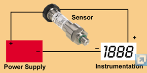
The sensor takes its power from the two wires in the form of a voltage and then regulates the current output (in the loop) in proportion to the sensor input: ie 4mA at zero input pressure and 20mA at 100% input. In order for the sensor to regulate, there is a minimum voltage needed, but also a maximum as the onboard voltage regulator can only dissipate a limited power.
The second element of the circuit is a “drop resistor”, which is normally built into the indicator, controller, input card or whatever. This resistor converts the current to a voltage (normal ohm’s law) which then processed by the A/D convertor, microprocessor etc. The most commonly used value for a drop resistor is 250ohms and there can be several of these units on one loop.
The third item in the loop is of course the power supply. This will be a standard DC supply: 24V DC is the most commonly used, but it is important to choose the right voltage.
To calculate the power supply value, a minimum and maximum calculation is required:
Vmin=sensor Vmin + (20mA*drop resistor)
Vmax=sensor Vmax + (4mA*drop resistor)
So, for example, if the sensor requires 12 to 35V and a 250ohm drop resistor is used:
Vmin=12+(20mA*250)=17V
Vmax=35+(4mA*250)=36V
Therefore a 24V DC supply can be used.
Read more: Index to all of our Technical Notes on Pressure
Interested in our strain gauge sensors? Let us call you…
Why Us?
- Suppliers of top quality strain gauge sensors and transducers to every corner of industry – UK and worldwide
- Over 100 years of expert transducer knowledge
- Our high quality products all come with a 3 year warranty